… AKA Part IV 🙂
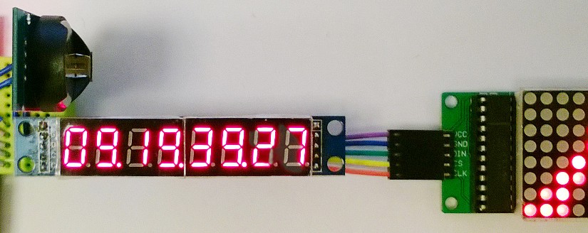
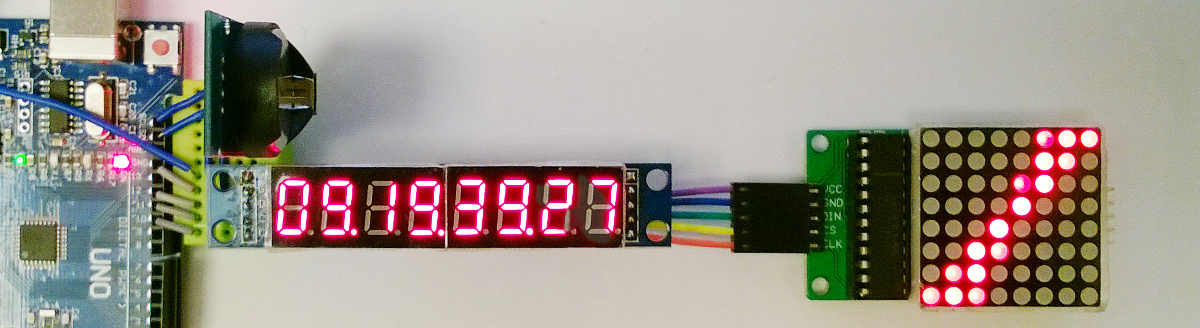
It is easy to stack up to 8 MAXIM MAX7219 ICs using the same 3 control lines. Natural idea would be to join 8 pieces of 8digits/7segmment displays (to get 64 digits – who needs 64 digits anyway?) or for instance 8 pieces of 8×8 LED matrices, obtaining 64×8, or may be 32×16, large matrix. I did something in between, stacking one 8digits display with one 8×8 matrix. On the matrix I decided to show rotating bar, to visualize passing seconds.
The most of the code, including libraries, and usage of interrupts was explained earlier in Parts III, II and I. The new element here is a second device, which we have to initialize in setup() procedure. Of course, also creating control object, we have to inform library, that 2 units were stacked up. As for programming side, there is 2D array (somehow not too often met in simple examples of arduino code).
See how it runs on YouTube
To make life easier, I prepared a small excel file, helping with generation of patterns to be displayed. See it on excel.bucki.pl
Each patter is displayed in a for loop, row by row (each row is a byte value, with single bits defining whether given LED is on or off).
See the code:
#include "LedControl.h"
#include <Wire.h>
#include <DS3231.h>
//CLK pin 10, CS pin 11, DIN pin 12
LedControl lc=LedControl(12,10,11,2); //2 devices connected
DS3231 Clock;

boolean update_display = true;

byte diodes [20][8] = {
{1, 2, 4, 8, 16, 32, 64, 128},{0, 1, 6, 8, 16, 96, 128, 0},
{0, 0, 3, 12, 48, 192, 0, 0},{0, 0, 1, 14, 112, 128, 0, 0},
{0, 0, 0, 15, 240, 0, 0, 0},{0, 0, 0, 204, 51, 0, 0, 0},
{0, 0, 0, 240, 15, 0, 0, 0},{0, 0, 128, 112, 14, 1, 0, 0},
{0, 0, 192, 48, 12, 3, 0, 0},{0, 128, 96, 16, 8, 6, 1, 0},
{128, 64, 32, 16, 8, 4, 2, 1},{64, 32, 32, 16, 8, 4, 4, 2},
{32, 32, 16, 16, 8, 8, 4, 4},{32, 16, 16, 16, 8, 8, 8, 4},
{16, 16, 16, 16, 8, 8, 8, 8},{8, 8, 16, 16, 8, 8, 16, 16},
{8, 8, 8, 8, 16, 16, 16, 16},{4, 8, 8, 8, 16, 16, 16, 32},
{4, 4, 8, 8, 16, 16, 32, 32},{2, 4, 4, 8, 16, 32, 32, 64}
};
// see excel file used to prepare 2D table on:
// http://excel.bucki.pl/8x8-display-planner/


void ReadDS3231() {
  static int oldsecond;
  static byte count;
  int second,minute,hour,hlast,mlast,slast;
  byte pattern;
  bool PM, h12;

  second=Clock.getSecond();
// this part executed only once in 100 calls only
  if ( second != oldsecond ) {
    count=0;
    oldsecond = second;
    minute=Clock.getMinute();
    hour=Clock.getHour(h12, PM);
    slast = second % 10;
    mlast = minute % 10;
    hlast = hour % 10;
    second = (second - slast) / 10;
    minute = (minute - mlast) / 10;
    hour = (hour - hlast) / 10;
    lc.setDigit(0,7,hour,false);
    lc.setDigit(0,6,hlast,true);
    lc.setDigit(0,5,minute,false);
    lc.setDigit(0,4,mlast,true);
    lc.setDigit(0,3,second,false);
    lc.setDigit(0,2,slast,true);
  }
  lc.setDigit(0,1,count/10,false);
  lc.setDigit(0,0,count%10,false);
  // left/right rotation during odd/even seconds
  if (second%2) {pattern = 19-count%20;} else {pattern = count%20;}
  for (byte j=0;j<8;j++) {
    lc.setRow(1,j,diodes[pattern][j]);
  }
  count++;
  update_display=false;
}

void setup() {
//clock
  Wire.begin(); //clock communication
//display
  lc.shutdown(0,false); //wake up MAX72XX
  lc.setIntensity(0,6); //set the brightness in range 0 - 15
  lc.clearDisplay(0);
  lc.shutdown(1,false); //wake up MAX72XX
  lc.setIntensity(1,6); //set the brightness in range 0 - 15
  lc.clearDisplay(1);

//interrupts
  cli();//stop interrupts for the time of setting timer1
    TCCR1A = 0;// set entire TCCR1A register to 0
    TCCR1B = 0;// same for TCCR1B
    TCNT1  = 0;//initialize counter value to 0
    OCR1A = 2499;// set compare match register = (16*10^6) / (x Hz * prescaler) - 1 (must be <65536)
    TCCR1B |= (1 << WGM12);   // turn on CTC mode
    TCCR1B |= (1 << CS11) | (1 << CS10);    // Set CS10 and CS11 bits for 64 prescaler
    TIMSK1 |= (1 << OCIE1A);  // enable timer compare interrupt
  sei();//allow interrupts
}

ISR(TIMER1_COMPA_vect){
update_display=true;
}

void loop() {
if ( update_display ) { ReadDS3231();}
//here other code doing something
}
Of course see also previous posts with DS3231 programs: (4digits, 8digits, 8digits with interrupts).
3 thoughts on “8×8 LED matrix as secondary display”