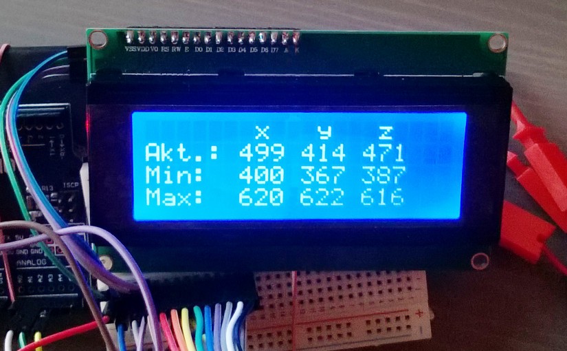
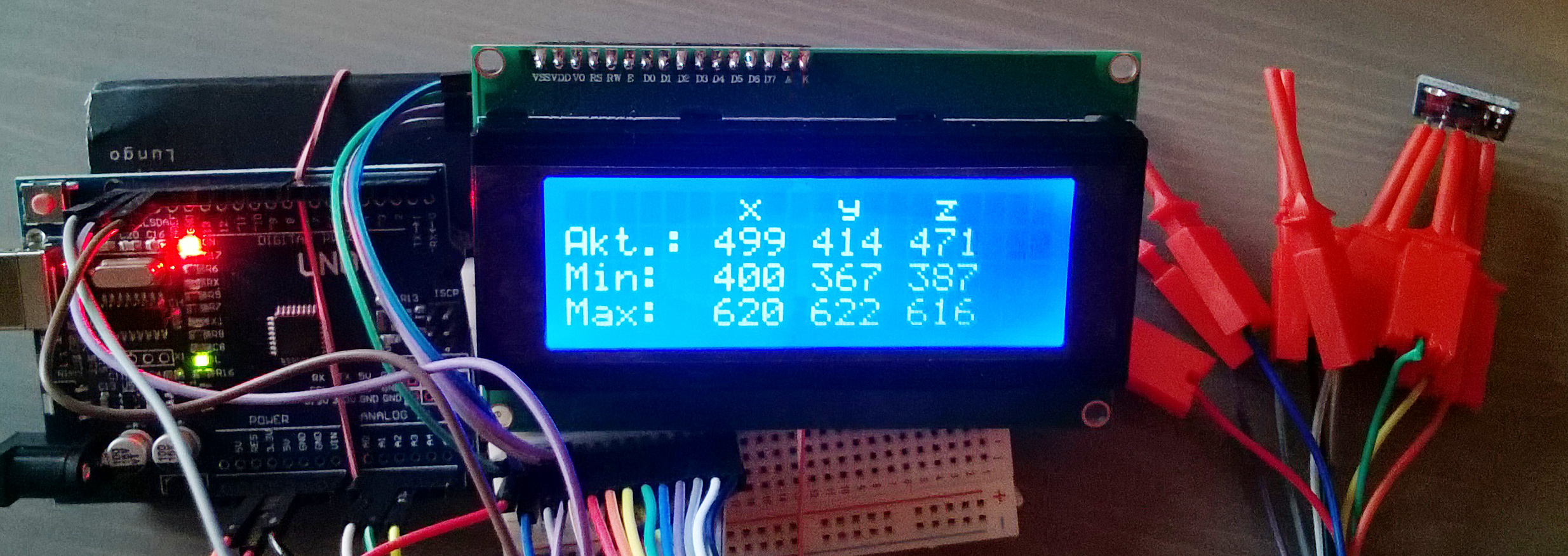
First tests of accelerometer ADXL335 using I2C controlled 20×4 LCD
For the tests I used already installed for 16×2 display module LiquidCrystal_I2C library (see distance meter and other posts)
The accelerometer IC itself is described on Analog Devices and has pretty simple interface when mounted on GY-61 board. There are just 3 connectors for each direction acceleration analog signals and power. It seems that one can power GY-61 module with 5V but I sticked to 3v3 and also used it as the reference voltage for analog input.
The code to find min/max values needed for calibration of the device.
#include <Wire.h>
#include <LiquidCrystal_I2C.h>
LiquidCrystal_I2C lcd(0x27,20,4);  // set the LCD address to 0x27 for a 16 chars and 2 line display

#define XPIN  A3
#define YPIN  A2
#define ZPIN  A1

int myx, myy, myz;
int maxx = 0, maxy = 0, maxz = 0;
int minx = 1024, miny = 1024, minz = 1024;

void setup() {
 analogReference(EXTERNAL);    // 3.3v -> AREF
 lcd.init();  lcd.backlight(); lcd.clear();
 lcd.print("       x   y   z");
 lcd.setCursor(0,1); lcd.print("Akt.:");
 lcd.setCursor(0,2); lcd.print("Min :");
 lcd.setCursor(0,3); lcd.print("Max :");
}

void loop() {
  myx = analogRead(XPIN);  // some suggest delay(2) after each read
  myy = analogRead(YPIN);
  myz = analogRead(ZPIN);

  minx = min(myx,minx); miny = min(myy,miny); minz = min(myz,minz);
  maxx = max(maxx,myx); maxy = max(maxy,myy); maxz = max(maxz,myz);

  lcd.setCursor(6,1);
  lcd.print(myx); lcd.print(" ");  lcd.print(myy);
  lcd.print(" "); lcd.print(myz); lcd.print("   ");
  lcd.setCursor(6,2);
  lcd.print(minx); lcd.print(" "); lcd.print(miny);
  lcd.print(" "); lcd.print(minz); lcd.print("   ");
  lcd.setCursor(6,3);
  lcd.print(maxx); lcd.print(" "); lcd.print(maxy);
  lcd.print(" "); lcd.print(maxz); lcd.print("   ");

  delay(50);
}
It seems that indeed 0G is around 511, and -1G/1G is around 110 from the 0G reading, so ca. 400/620 – see picture,
Next steps could include combining this sensor with HMC5883 on GY-273 board
It will be easy, because GY-273 board uses I2C interface (non-conflicting address with LCD controlling module), and with A1-A3 ocupied by GY-61, and A4 and A5 by I2C module we have only A0 available (on UNO board).