8×8 LED matrix as secondary display

… AKA Part IV 🙂

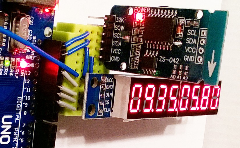
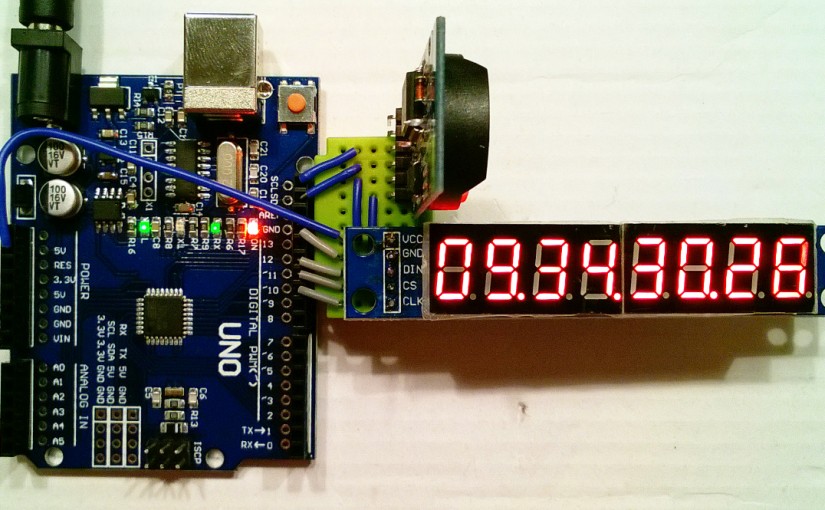
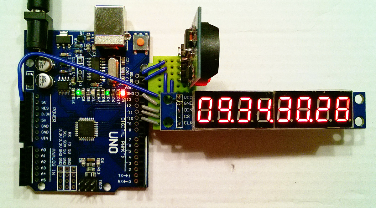
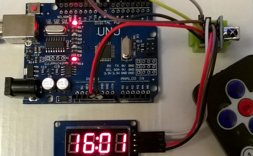
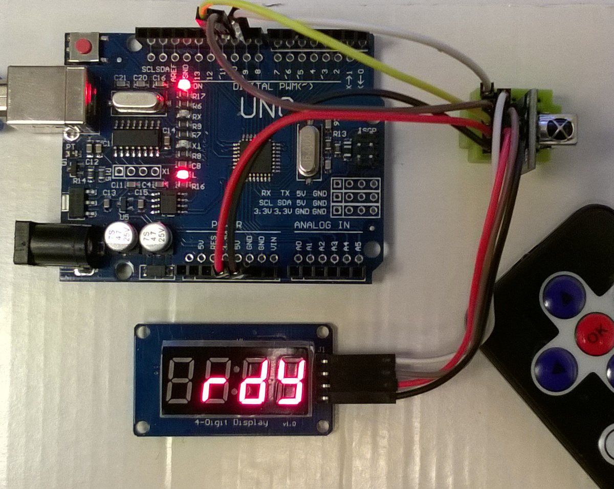
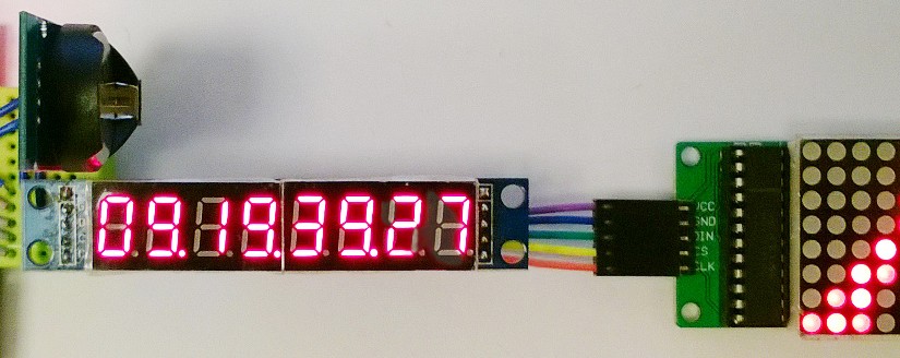
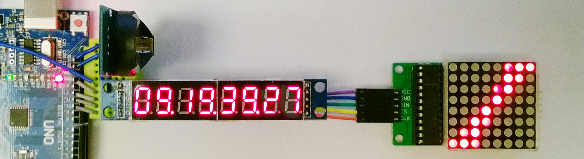
It is easy to stack up to 8 MAXIM MAX7219 ICs using the same 3 control lines. Natural idea would be to join 8 pieces of 8digits/7segmment displays (to get 64 digits – who needs 64 digits anyway?) or for instance 8 pieces of 8×8 LED matrices, obtaining 64×8, or may be 32×16, large matrix. I did something in between, stacking one 8digits display with one 8×8 matrix. On the matrix I decided to show rotating bar, to visualize passing seconds.

8digit_8x8

The most of the code, including libraries, and usage of interrupts was explained earlier in Parts III, II and I. The new element here is a second device, which we have to initialize in setup() procedure. Of course, also creating control object, we have to inform library, that 2 units were stacked up. As for programming side, there is 2D array (somehow not too often met in simple examples of arduino code).

See how it runs on YouTube

Continue reading 8×8 LED matrix as secondary display

DS3231 MAX7219 interrupts

… also known as DS3231 part III. (Have you seen Part I and Part II ?)

zegar1

It is pretty natural to start playing with interrupts as we write program for the clock. There are 3 (in UNO, other boards have different number) internal timer based interrupts. Timer0 and Timer2 are based on 8 bits counters, so I decided to use Timer1 here with 16 bits. The prescaler set to 64 and match register to 2499 did the trick (one could use as well 256;624 or 8;19999 pairs for Timer1 looking for 100Hz refresh).

Continue reading DS3231 MAX7219 interrupts

DS3231 MAX7219 8digits

… or DS3231 part II 🙂 (see also part III and IV – the story goes on with interrupts)

The next step after testing if it works at all was to display ful time, and especially seconds. So 4 digits offered by TM1637 based module (let’s call it part I) was not enough. I used 8 digits 7 segment display based on MAX7219.


maxim-clock1

For the code, apart from DS3231 library mentioned in previous post, I used also Eberhard Fahle LedControl library.

Continue reading DS3231 MAX7219 8digits

ADXL335 I2C 2004 LCD

First tests of accelerometer ADXL335 using I2C controlled 20×4 LCD

Akcel_2004

For the tests I used already installed for 16×2 display module LiquidCrystal_I2C library (see distance meter and other posts)

The accelerometer IC itself is described on Analog Devices and has pretty simple interface when mounted on GY-61 board. There are just 3 connectors for each direction acceleration analog signals and power. It seems that one can power GY-61 module with 5V but I sticked to 3v3 and also used it as the reference voltage for analog input. Continue reading ADXL335 I2C 2004 LCD

DS3231 AT24C32 TM1637 4digits

DS3231 clock with AT24C32 memory connected to TM1637 controlled 4digits 7segment display. This is first step in using DS3231 clock – see also next steps with 8 digits 7 segment display and with use of internal timer interrupts and with combining two display types)

clock4dig

As you can see all setup was arranged on Proto Shield with SYB-170 breadboard. This way, it can be easily dismounted from UNO base, and left aside. Then, once you want to use UNO board for another project you can take it, and once you want return to this one, the shield has to be slided onto UNO, code written back to the board, and everything works back again :-). As I often switch between the projects, I do like this approac, and have at least 2 proto shields loaded with some parts and finished_but_may_return_to projects on them 🙂 )

Continue reading DS3231 AT24C32 TM1637 4digits

HC-SR04 and 1602

Simple ultrasonic sensor module HC-SR04 and 1602 LCD display were combined into useable digital yardstick.

Two versions of the sensor module from different suppliers worked similar way. The right one sometimes (name printed in the middle) had sometimes tendency to keep once entered “out of range” state forever. Simple transistor to switch on/off VCC did the trick – if the “out of range” state was longer than 1 second the module was switched off and switched on back.

HC-SR04_2types

The sensor is ooperated by standard Arduino commands, and  the display is controlled by the object from LiquidCrystal_I2C library https://bitbucket.org/fmalpartida/new-liquidcrystal/downloads/LiquidCrystal_V1.2.1.zip

Continue reading HC-SR04 and 1602

TM1637 4 digits

This is pretty simple 4 digits (and a colon between 2-digit groups) display. Natural use would be to display time (see here), but I decided to show a sample used for IR Remote codes testing.

1637rdy

Here is the initial state before anything was sent to the receiver.

Label Ready 😉 was obtained by adressing single segments (as described for instance in document on forum.arduino.cc

Continue reading TM1637 4 digits

LCD Keypad Shield

A display and buttons shield (but BTW: have you checked other Displays on this site?) well suited as the human interface for a number of “compact design standalone” projects.

LCDShield

Similar to already described 16×2 LCD module (using the same display), but with 6 built into the shield buttons (RESET, SELECT; and 4 directions: LEFT, UP, DOWN, RIGHT).

The shield leaves a lot of pins at your disposal. Used pins are only:

Analog 0 Button (select, up, right, down and left – see the code comments)
Digital 4 – 7 DB4 – DB7
Digital 8 RS (Data or Signal Display Selection)
Digital 9 Enable
Digital 10 Backlit Control

So the user has free access to Analog 1-5, and Digital 0-3 and 11-13. Out of these, the most important are 0 and 1, which can be used as RX and TX, 3 and 11 with are PWM capable, as well as standard LED 🙂 output on digital pin 13.

Also whole ISCP connector, which is normally blocked by the shield body is repeated on the side.

Continue reading LCD Keypad Shield

IR Remote

Standard set for Arduino kits consists of simple remote and a small module with IR receiver (basically just TSOP38238 IR sensor + LED and resistor).

IRRemote

The connection and first steps of decoding the signal is based on Ken Shirriff’s blog and his IRemote library. The library is available at Github

See also how decoded key number can be displayed on LED display, and please note, that green LED on the picture is not used in the code below. Continue reading IR Remote