Basic setup to test HMC5883 on GY-273
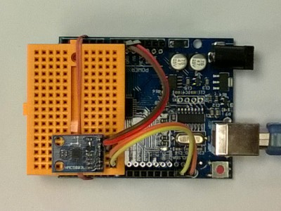
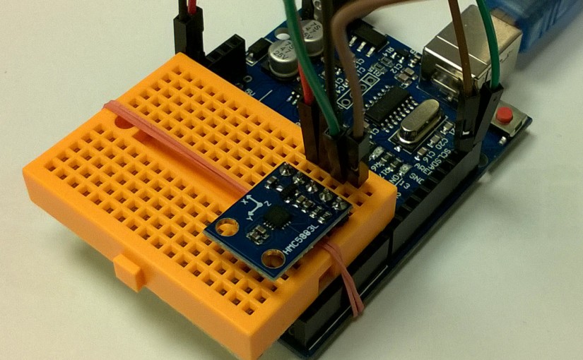
Real images:
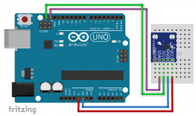
Just connect: GND, VCC (5V), SCL and SDA (I2C standard signals) to your Arduino. Older versions could use A4 for SDA and A5 for SCL, but with most up-to-date boards appropriate dedicated pins (see green and purple connection lines) could be used,
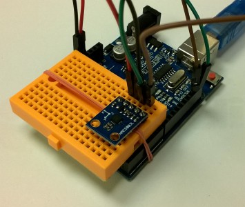
And another image with shorter connectors: Code for first tests ( based on http://www.inmotion.pt/documentation/sparkfun/6/SEN-10530/HMC5883.pde )
/*
An Arduino code example for interfacing with the HMC5883

by: Jordan McConnell
 SparkFun Electronics
 created on: 6/30/11
 license: OSHW 1.0, http://freedomdefined.org/OSHW

Analog input 4 I2C SDA
Analog input 5 I2C SCL
*/

 /*
  * adopted to Wire library version distributed with Arduino IDE 1.0 and later
  * where send() and receive() have been replaced with read() and write(). ( by
  * Janusz Bucki November 2015
  */

#include <Wire.h> //I2C Arduino Library

#define address 0x1E //0011110b, I2C 7bit address of HMC5883

void setup(){
  //Initialize Serial and I2C communications
  Serial.begin(9600);
  Wire.begin();

  //Put the HMC5883 IC into the correct operating mode
  Wire.beginTransmission(address); //open communication with HMC5883
  Wire.write(0x02); //select mode register
  Wire.write(0x00); //continuous measurement mode
  Wire.endTransmission();
}

void loop(){

  int x,y,z; //triple axis data
  int xmin,xmax,ymin,ymax,zmin,zmax;
  xmin=0; xmax=0; ymax=0; ymin = 0; zmin=0;zmax=0;
  //Tell the HMC5883 where to begin reading data
  Wire.beginTransmission(address);
  Wire.write(0x03); //select register 3, X MSB register
  Wire.endTransmission();


 //Read data from each axis, 2 registers per axis
  Wire.requestFrom(address, 6);
  if(6<=Wire.available()){
    x = Wire.read()<<8; //X msb
    x |= Wire.read(); //X lsb
    z = Wire.read()<<8; //Z msb
    z |= Wire.read(); //Z lsb
    y = Wire.read()<<8; //Y msb
    y |= Wire.read(); //Y lsb
  }

  //Print out values of each axis
  Serial.print("x: ");
  Serial.print(x);
  Serial.print("  y: ");
  Serial.print(y);
  Serial.print("  z: ");
  Serial.println(z);

  delay(250);
}


One thought on “HMC5883 GY-273 test”